TS-50 serial interface
 This article describes a homebuilt interface for connecting the TS-50 transceiver to a computer using the serial port.
Note: this article is depreciated, for a more modern and easier way to interface the TS-50 to a computer, please check the post TS-50 USB interface.
Although the Kenwood TS-50 transceiver doesn’t have a serial interface, it can be interfaced to the computer for CAT (computer aided tuning) control using optional Kenwood accessories. This allows the rig to be controlled by the log book software, so you do not have to give attention to band and mode changes. When you change the band or mode on the rig, the log book software detects this and will log the correct band or mode automatically. When you click a DX spot in your log book software, the radio will automatically be switched onto the correct frequency and in the correct mode, making DX hunting really easy. I use DX4WIN software, the web site gives a good example of how to use CAT control.
The problem with interfacing the TS-50 is that Kenwood charges almost 200€ for its CAT solution (your mileage may vary). You’ll need to buy both the IF-10D and the IF-232 unit to interface your TS-50. I figured these two units should be easy to homebrew.
IF-10D
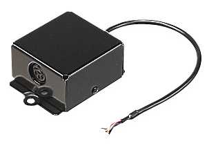
This unit plugs into the CN6 connector, which can be found by removing the black plastic disk on the bottom front of the TS-50. The unit can be screwed to the side of the rig.
It contains a 74LS04 chip, that inverts the serial signals to/from the unit (RxD, TxD, RTS, CTS). The pigtail in the picture is terminated onto a small white connector, which connects to connector CN6 on the TS-50. This is the pigtail with Kenwood part number E30-3165-05 discussed below.
IF-232
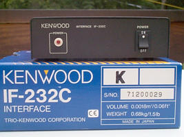
The IF-232 plugs into the IF-10D’s 6 pin DIN connector on one side, and connects to the computer’s serial port using the DB9 plug on the back of the unit. This is a universal unit, which can also be used with other Kenwood radios.
It features a MAX232 chip, that converts the serial signals from the IF-10D (TTL level 0/+5V) into RS-232 signal level (-10V/+10V) for the computer. Although I haven’t tested this, I believe the IF-232 inverts the serial signals. I believe the TS-850 needs to be fed inverted serial signals, while the TS-50 needs non-inverted signals. That is why the IF-10D needs to be used after the IF-232, to invert the signals back to their non-inverted state.
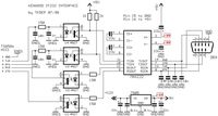
The interface
When investigating the workings of the IF-10D and the IF-232 it occurred to me that the diagram that TK5EP built for his TS-850, should work with the TS-50 as well. I built a test version without the optocouplers, and it works. Of course you will need to replace the TS-850’s ACC1 connector with the TS-50’s CN6 connector, with the correct pinout. Kenwood part number “E30-3165-05 IF-10D CONNECTING WIRE W/CONN. 6P” is a 15 cm pigtail with a male connector that fits the CN6 connector on the TS-50 main board. You can find this part at East Coast, although it was discontinued last time I looked. There are reports from other hams who confirm they were able to scavenge a similar connector from old computers and adapt the connectors so they would fit.
Troubleshooting
When you are troubleshooting the circuit, you might find this info useful:
-
The TS-50’s serial settings are 4800 baud, 1 start bit, 8 data bits, 2 stop bits, no parity, hardware handshaking.
-
As for ‘the more expensive interfaces’; the Kenwood IF-232 seems to convert RS-232-level to and from TTL-level, and in addition inverts all 4 signals. That’s where the IF-10D comes into play; it is used to invert the signals again, so basically if we homebrew the circuit, we don’t need any inverters. The TS-50 can be connected to RS-232 without inverting any signals, just signal conversion from RS-232 to-and-from TTL-level is needed. A MAX-232 will handle this just fine. Forget about the 74LS04 inverter chip that you see in some circuit diagrams, it is not needed and won’t work.
-
All that is needed is a single MAX-232 chip. Even if you have a clear circuit diagram, read the datasheet. I said; read the datasheet! The MAX-232 has different versions, and they all seem to differ a bit in configuration (as opposed to Maxim’s MAX-232, my Intersil HIN232 clone uses 4x 1µF caps instead of 10µF caps for Maxims chips. This does make a difference!
-
Since the Kenwood uses hardware handshaking, the CTS and RTS lines come into play. You can get them out of the troubleshooting process by just looping them (connect RTS to CTS at the radio side, and also connect RTS to CTS at the computer side. Don’t connect them all 4 together!) The circuit will then work fine with just the RxD and TxD signals.
-
A scope with 5 V/DIV and .2mS/DIV will trace the serial signals just fine.
-
The TS-50 outputs a bitstream when you send it a bitstream. I originally tried to send commands on a serial terminal program(Hyperterminal), but got no response. Althoug this makes no sense to me, I found a terminal program to be useless to try to control the rig. It will work good for troubleshooting using loops though.
-
I used the DOS program RIG-EQF for testing. Other Kenwood-compatible CAT programs should work as well.
-
Although the MAX-232 chip only uses 10mA, I recommend not to power the circuit off pin 5 on connector CN6 inside the TS-50. A wiring mistake or short is easily made, and we don’t want to risk damaging our rig. Use a 7805 regulated power supply instead.
-
The best way to build the circuit is on prototype board (the white type with spring contacts). First, build the 7805 regulated power supply, and test the voltage. Then insert the MAX-232 into the board, and the 4 charge pump caps. Measure the voltages across the 2 caps that are connected to ground and +5V. They should read close to +10V and -10V on them. Anything above 8V should be fine. Then connect the computer’s serial port to the MAX-232’s TxD & RxD pins, and loop them on the pins before entering the MAX-232. Loop the RTS & CTS pins as well. If you type a character in your terminal program, it should be sent back by the loop. Now you know your serial cable/terminal program/comport is working. Then loop the MAX-232’s TxD & RxD pins on the TTL end (after the level conversion takes place), and check if the loop trick works again. You now know that the conversion inside the MAX-232 is working. Now connect the TS-50 to the outputs, and loop the radio’s RTS & CTS pins as well. Now try to connect with RIG-EQF or another CAT program. If it doesn’t work, first try reversing the TxD & RxD pins. Troubleshoot & debug as needed Now try to run the RTS and CTS signals through the MAX-232 until everything works again. The TS-50 will need them to let the computer know it is getting swamped by data.
I can understand the philosophy of Kenwood who try to make a lot of money out of the IF-232 and IF-10D circuits, but don’t be taken in by them… Thanks to the Yahoo! TS-50 group for helping me sort this one out!
Resources
- IF-10D Service Manual (and circuit diagram)
- IF-10D manual
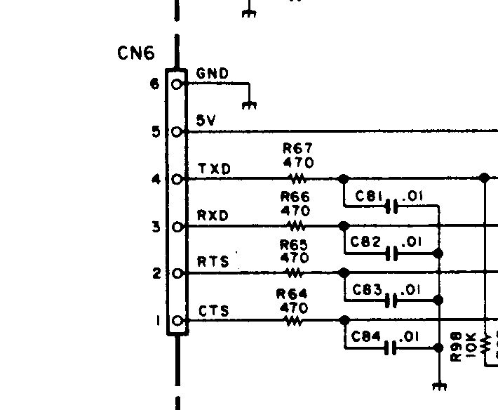
- Pinout for the TS-50’s CN6 connector
- Excerpt from the schematic diagram, showing processor to CN6 connection
You might also want to check out my RS-232 to TTL converter board with MAX232 page, since it is basically the same circuit (except for the optocouplers).